10+ define uml diagram
The newpage keyword is used to split a diagram into several images. 版型通过类关键字来定义 你可以使用note left of note right of note top of note bottom of这些关键字来添加备注.

Unified Modeling Language Wikiwand
你还可以在类的声明末尾使用note left note rightnote top note bottom来添加.

. Instead Sender refers to the Handler interface for handling a request handlerhandleRequest which makes the Sender independent of which receiver handles the request. Right-click on the project node in Solution Explorer and select Open Visual Paradigm from the popup menu. This title overrides the previously specified title if any.
Communication diagram is a new name added in UML 20. The Unified Modeling Language UML is a general-purpose developmental modeling language in the field of software engineering that is intended to provide a standard way to visualize the design of a system. Some paradigms are concerned mainly with implications for the execution model of the language such as allowing side effects or whether the sequence of operations is defined by the execution modelOther paradigms are concerned.
Added the ability to define a hierarchy and decompose a software system into components and sub-components. Set the deadline and keep calm. Get all these features for 6577 FREE.
Focuses on the actions from a user perspective. In this example the. Reactive systems can be defined as a system that responds to external or internal events.
Additional elements can be added wherever required. A programming language is any set of rules that converts strings or graphical program elements in the case of visual programming languages to various kinds of machine code output. Located at the southern tip of New York State the city is the center of the New York metropolitan area the largest metropolitan area in the world by urban landmass.
UML Use Case Diagram. The center topic of todays discussion is the Use Case diagrams. Timing Diagram A timing diagram is a type of behavioral or interaction UML diagram that focuses on processes that take place during a specific period of.
This is very handy with Word to print long diagram on several pages. Receive your papers on time. A component in UML is shown in the following figure with a name inside.
Communication diagram is a structural view of the messaging between objects taken from the Collaboration diagram concept of UML 14 and earlier versions. Programming paradigms are a way to classify programming languages based on their features. The concepts behind it are about organizing the way a device computer program or other often technical process works such that an entity or each of its.
Statechart diagram is one of the five UML diagrams used to model the dynamic nature of a system. UML short for Unified Modeling Language is a standardized modeling language consisting of an integrated set of diagrams developed to help system and software developers for specifying visualizing constructing and documenting the artifacts of software systems as well as for business modeling and other non-software systemsThe UML represents a collection of best. The Receiver1 Receiver2 and Receiver3 classes implement the Handler interface by.
This can be defined as a modified version of collaboration diagram. In UML 1x a guard could only be assigned to a single message. The creation of UML was originally motivated by the desire to standardize the disparate notational systems and approaches to software design.
The original UML specified nine diagrams. Diagrams have been used since prehistoric times on walls of caves but became more prevalent during the Enlightenment. In the above UML class diagram the Sender class doesnt refer to a particular receiver class directly.
What advantages do you get from our course help online services. 85 10 average quality score from customers. Therefore the process of data modeling involves professional data modelers working closely with business stakeholders as well as potential users of the information system.
Such a diagram would illustrate the object-oriented view of a system. Guards are used throughout UML diagrams to control flow. Create a C library project Map Viewer in Visual Studio.
A node in UML is represented by a square box as shown in the following figure with a name. 10 years in academic writing. Citation needed Programming languages are one kind of computer language and are used in computer programming to implement algorithmsMost programming languages consist of instructions.
The object orientation of a system is indicated by a class diagram. Class Diagram The most widely use UML diagram is the class diagram. When it comes to system construction a class diagram is the most widely used diagram.
Must contain at least 4 different symbols. Any Deadline - Any Subject. Essay Help for Your Convenience.
In software engineering an ER model is commonly formed to represent things a business needs to remember in order to perform business processesConsequently the ER model becomes an abstract data model that defines a data or information structure which can be implemented in a database typically a relational database. UML Class Diagrams is a type of static structure diagram that is used for general conceptual modeling of the systematics of the application. Statechart diagrams are useful to model the reactive systems.
The main aim of UML is to define a standard way to visualize the way a system has been designed. It is the building block of all object oriented software systems. Design system with UML Class Diagram.
A diagram is a symbolic representation of information using visualization techniques. Interaction Overview diagram is also a new addition in UML 20. A new diagram is created.
Instead the Creator refers to a separate factoryMethod to create a product object which makes the Creator independent of which concrete class is instantiated. New York often called New York City NYC to distinguish it from the State of New York is the most populous city 2 New York City is also the most densely populated major city in the United States. UML state machine also known as UML statechart is an extension of the mathematical concept of a finite automaton in computer science applications as expressed in the Unified Modeling Language UML notation.
To draw a guard on a sequence diagram in UML 1x you placed the guard element above the message line being guarded and in front of the message name. Focuses on the business requirements and many more. In Diagram Navigator right-click on class diagram and select New Class Diagram from the popup menu.
6 to 30 characters long. They define different states of an object during its lifetime and these states are changed by events. Here I will discuss guards in both UML 1x as well as UML 2.
Sometimes the technique uses a three-dimensional visualization which is then projected onto a two-dimensional surface. Focuses more on the process from a system perspective. It is quite similar to blueprints used in other fields of engineering.
Component is used to represent any part of a system for which UML diagrams are made. Data modeling is a process used to define and analyze data requirements needed to support the business processes within the scope of corresponding information systems in organizations. ASCII characters only characters found on a standard US keyboard.
UML is not a programming language. Entityrelationship modeling was developed for. This really does work.
We cover any subject you have. UML 2x brings that number up to 13. The word graph is sometimes used as a synonym.
9712 orders delivered before the deadline. You can put a title for the new page just after the newpage keyword. Focuses more on the blueprint.
In the above UML class diagram the Creator class that requires a Product object does not instantiate the Product1 class directly. All our academic papers are written from scratch. Subclasses of Creator can redefine which class to instantiate.
Languages can be classified into multiple paradigms. 1091 The best writer.
Cs 383 Software Engineering

Unified Modeling Language Wikiwand

Class Diagram Wikiwand
What Is Activity Diagram In Uml Quora
Cs 383 Software Engineering
Cs 383 Software Engineering
What Is Meant By Uml Diagram Quora

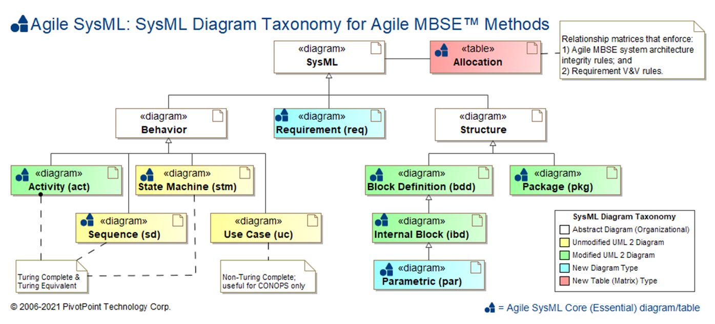
Sysml Faq What Is Sysml Who Created Sysml
What Is Meant By Uml Diagram Quora
What Does The Uml Diagram Capture Quora

Class Diagram Wikiwand
What Is The Difference Between A Uml Diagram And A Class Diagram Quora
How Do We Read Cardinality In A Uml Diagram Or In E A Diagram Quora
Cs 383 Software Engineering
What Are The Different Uml Diagrams Quora

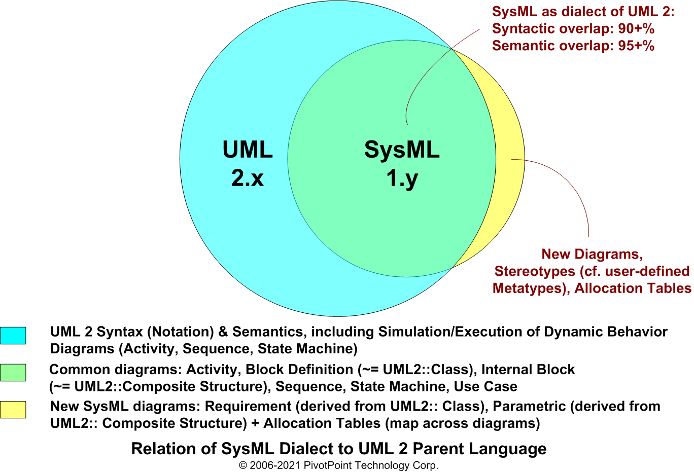
Sysml Faq Can Sysml And Uml Be Combined In Same Model
Cs 383 Software Engineering